Instrument Cluster
Published on: ; Finished on:
Summary
The gauge cluster in the BMW E36 is a very interesting piece of hardware. This page will document the process of rebuilding the cluster, and the design choices made along the way.
Introduction
The gauge cluster in the BMW E36 is a fascinating piece of hardware, featuring a variety of gauges and an LCD display managed by a PCB mounted on its back. As part of the EV conversion for the BMW Z3, the gauge cluster was rebuilt to enhance its functionality. This page documents the process and design choices involved in the rebuild. For a deeper dive into the technical details, the complete firmware and related files are hosted on the eZ-Green GitHub repository, where enthusiasts are welcome to explore and contribute.
Gauge motors
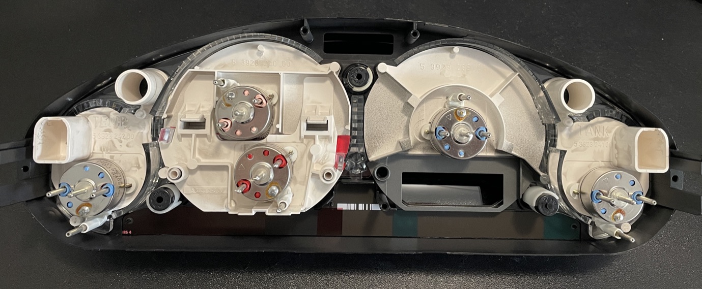
Air-core stepper motor
The air-core stepper motor used in the BMW E36 gauge cluster features two coil pairs, one sine pair and one cosine pair, resulting in four terminals per motor. The angle of the needle is determined by the ratio of the magnetic field and the current flowing through the coils.
The direction θ of the overall magnetic field is approximately:
Where x and y are the sine and cosine currents, respectively. So if we want to set the angle θ, we can calculate the coil currents:
Than x and y can be used to calculate the duty cycle of the PWM signal for each coil pair, by multiplying them by the maximum duty cycle (255 for 8-bit PWM), or by using a lookup table (LUT) generated with Python.
Driving the motors
During initial testing, a 5V voltage was found to work well for driving these motors, resulting in a 17mA current flow, which we consider acceptably low. However, to have better control over the current, we wil later try to modulate it using Pulse Width Modulation (PWM), allowing for easy adjustments in the future.
Using H-bridge motor drivers
Each coil pair requires an H-bridge motor driver, making a total of two H-bridges needed for the air-core stepper motor. For initial testing, the HW-095 double H-bridge module was found to work effectively at 5V. For the final design, the TOSHIBA TC78H621FNG(O,EL) motor driver was chosen, as it contains a dual H-bridge setup (datasheet).
This motor driver chip has an Enable (EN) and a Phase (PHA) pin for each bridge. By using PWM on the EN pin, the output can be set when the pin is High, or put into High impedance mode when the pin is Low. The PHA pin is used to control the half of the sine/cosine phase that the coils are in, allowing for precise control over the motor's position.
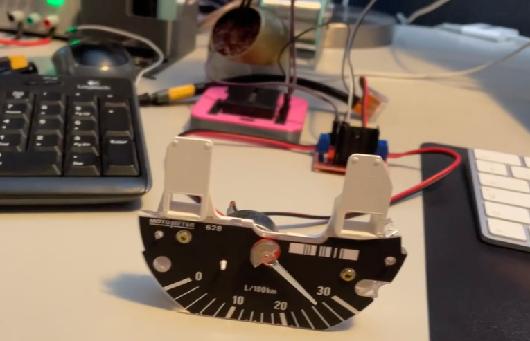
Controlling an Air Core Gauge with Arduino and H-bridge
In The test project, the air core gauge is controlled using an Arduino and an H-bridge. The Arduino code reads the desired angle from the serial monitor and moves the air core gauge to the specified angle. The sine and cosine currents needed to position the gauge are found using a lookup table (LUT) generated with Python.
Designing the Controller Layout for the Gauge Cluster
Our gauge cluster boasts an impressive array of components: a display screen, five individual gauges, a user interface button, and a set of yet-to-be-determined lights. Note that not all the lights will be managed by the electronic systems. The display content will be driven by data collected from a pulse counter and the CAN-bus system. To handle these sophisticated functions, we have opted to use an ESP32 System on a Chip (SoC). During the prototyping stage, we are using an Adafruit Feather board as a stand-in for the ESP32. This powerful SoC will support a CAN-bus peripheral and an OLED display screen, both connected via the SPI interface. We'll also employ one of the ESP32's GPIO pins as a pulse counter and a button controller. In addition to the above, the ESP32 will be responsible for communicating with an RP2040 microcontroller. The RP2040, in turn, will manage the operation of the gauges and the warning light systems.
Dial Face
A new dial face is made because some of the original markings are no longer accurate with an EV conversion. The new dial face is made from inkjet transparency film, which has spray paint applied in various layers to create the markings. This section describes the process of making the dial face.
Design and Production
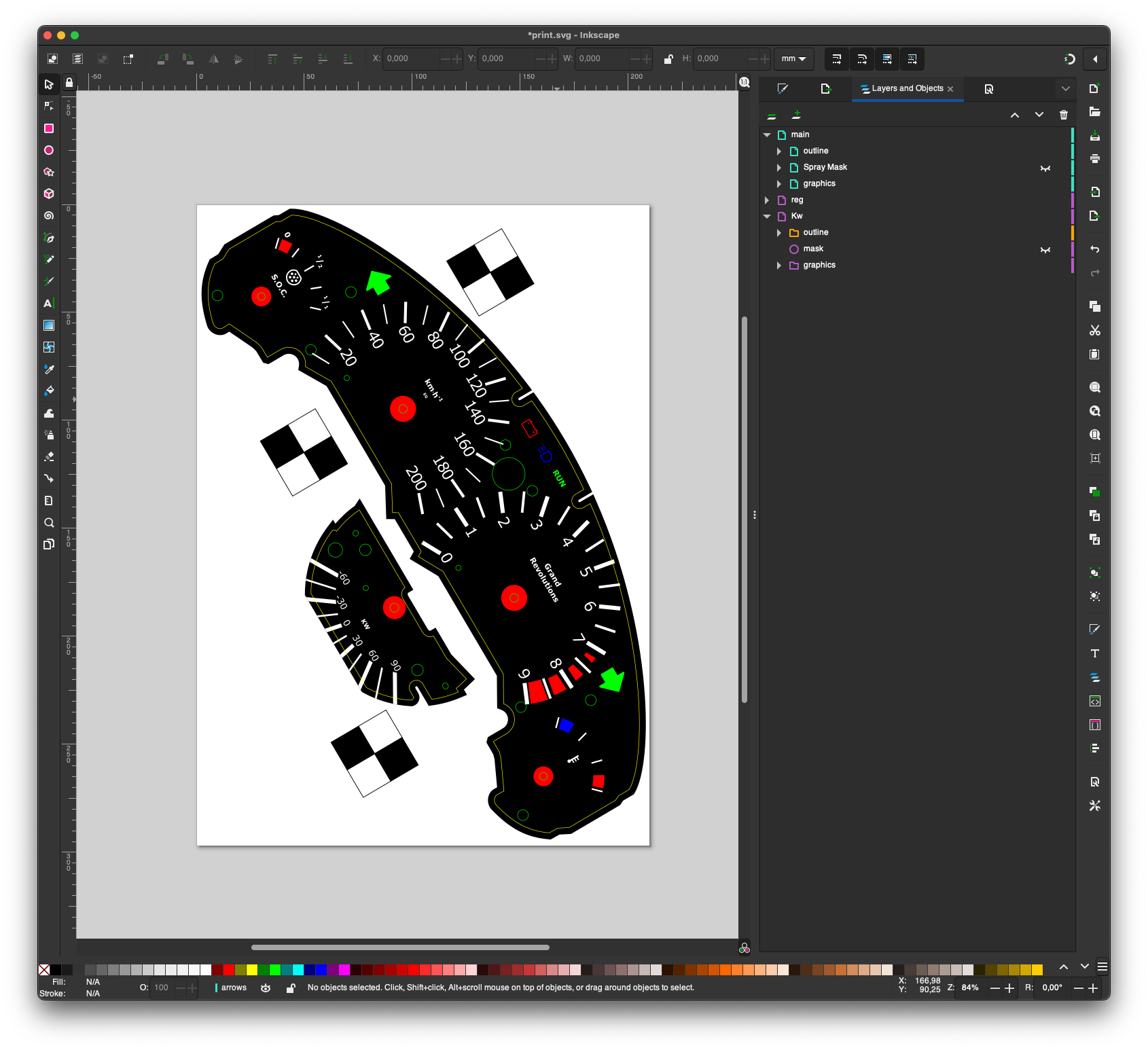
The design was done in Inkscape, a furure version of the design could be progematicly designed using Python, so that the design can be easily modified for different layouts, such as easily chainging the number of revs and ware the redline is.
here we desctive the design proces
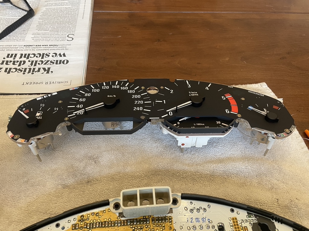
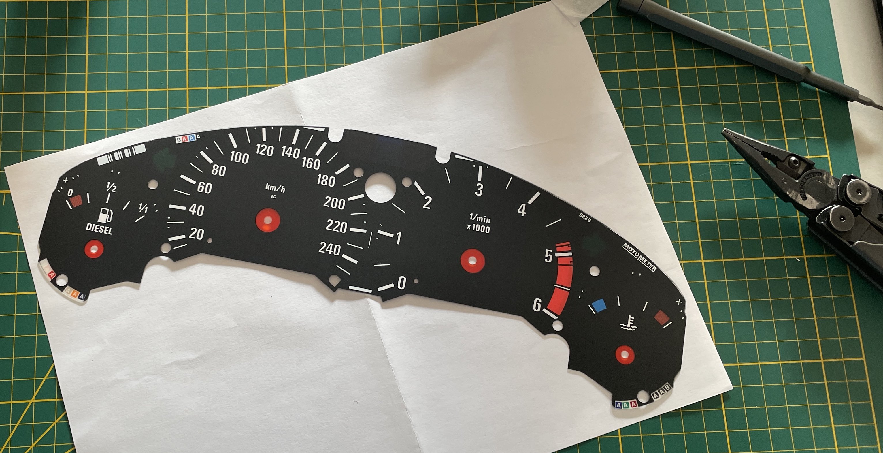
Scanning the Original Dial Face
To begin, we disassembled the instrument cluster to remove the original dial face. Then, we scanned it at the highest resolution possible to digitize the image for further modifications.
Redesigning the Dial Face
We used Inkscape to draw the outline and the necessary holes to be cut. We designed new graphics and created a layer with a mask for stickers that would be cut out on a vinyl cutter to serve as a spray paint mask.
Layer Stack-Up
For the substrate, we used inkjet-compatible transparency sheets. We printed the graphics layer on the top (the sticky side) and set my printer to think it was printing on photo paper to achieve the highest resolution and ink saturation. To protect the ink layer and make the unprinted parts less sticky, we applied a transparent matte finish spray on the top. The white parts of the graphic remained transparent, so we applied white spray paint to the back side to make them white.
When the headlights of the car are turned on, the illumination of the dial face is activated. However, because the light passing through the dial face should be red, a red layer of spray paint was also applied to the back. Finally, we removed the stickers from the back to reveal the areas where no spray paint was applied.
Production
Here we describe the production process
Printing the Graphics
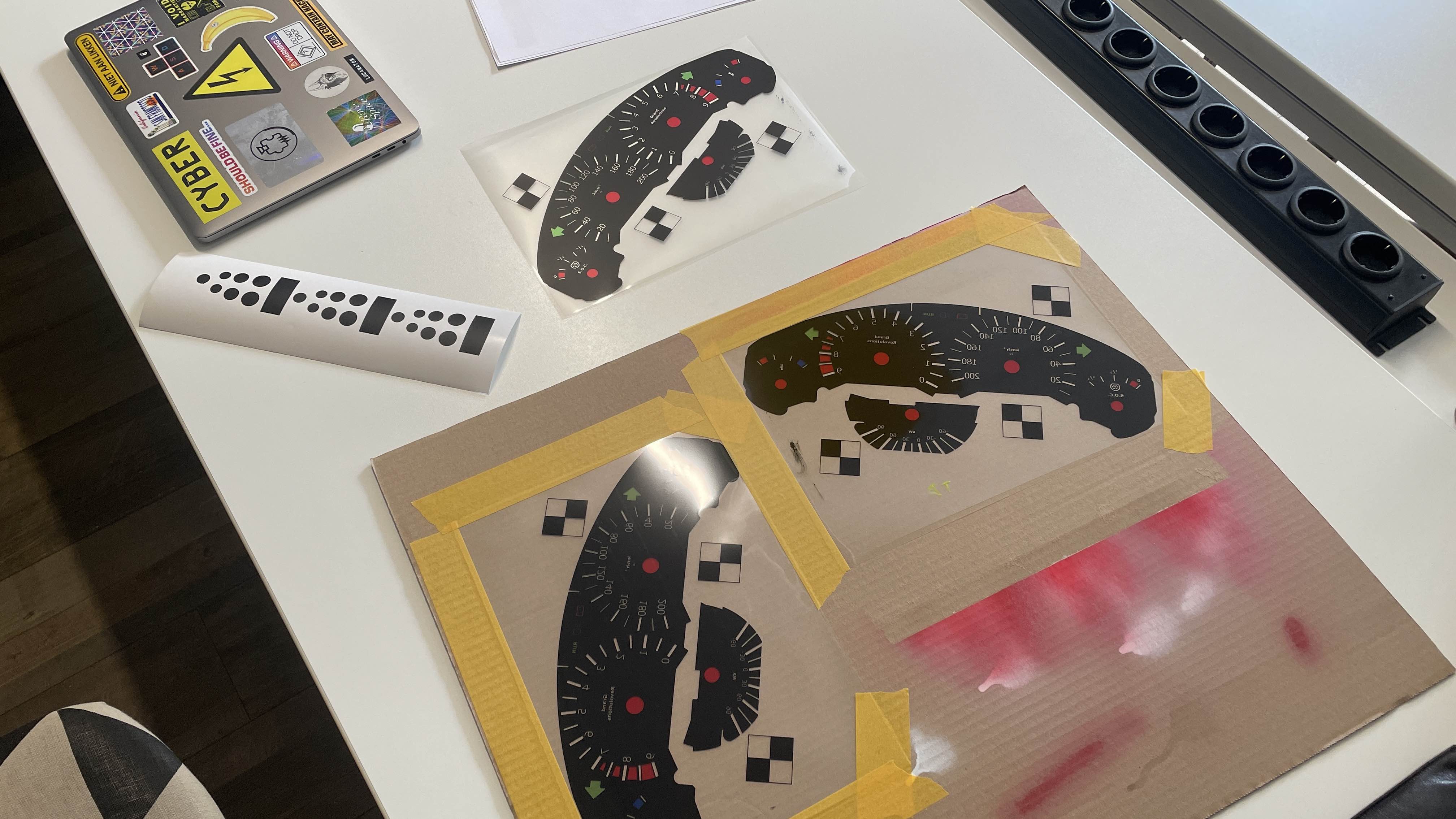
As mentioned above, we printed the graphics layer on the top (the sticky side) of Inkjet-compatible transparency sheets. We set the printer to think it was printing on photo paper to achieve the highest resolution and ink saturation. To protect the ink layer, make the unprinted parts less sticky, and reduce reflaction, we applied a transparent matte finish spray on the top.
background and transparancy
Some parts of the dial face should be white, but some of the colord parts, such as the icons on top and the tamperature light should rebain semi transparant. To achieve this, we applied vinal stickers as a mask to the backsice of the dile. The stickers were cut out on a vinyl cutter.
Than a white layer of spray paint was applied to the back side to make the white parts white. Followed by a red layer of spray paint to make the light passing through the dial face red.
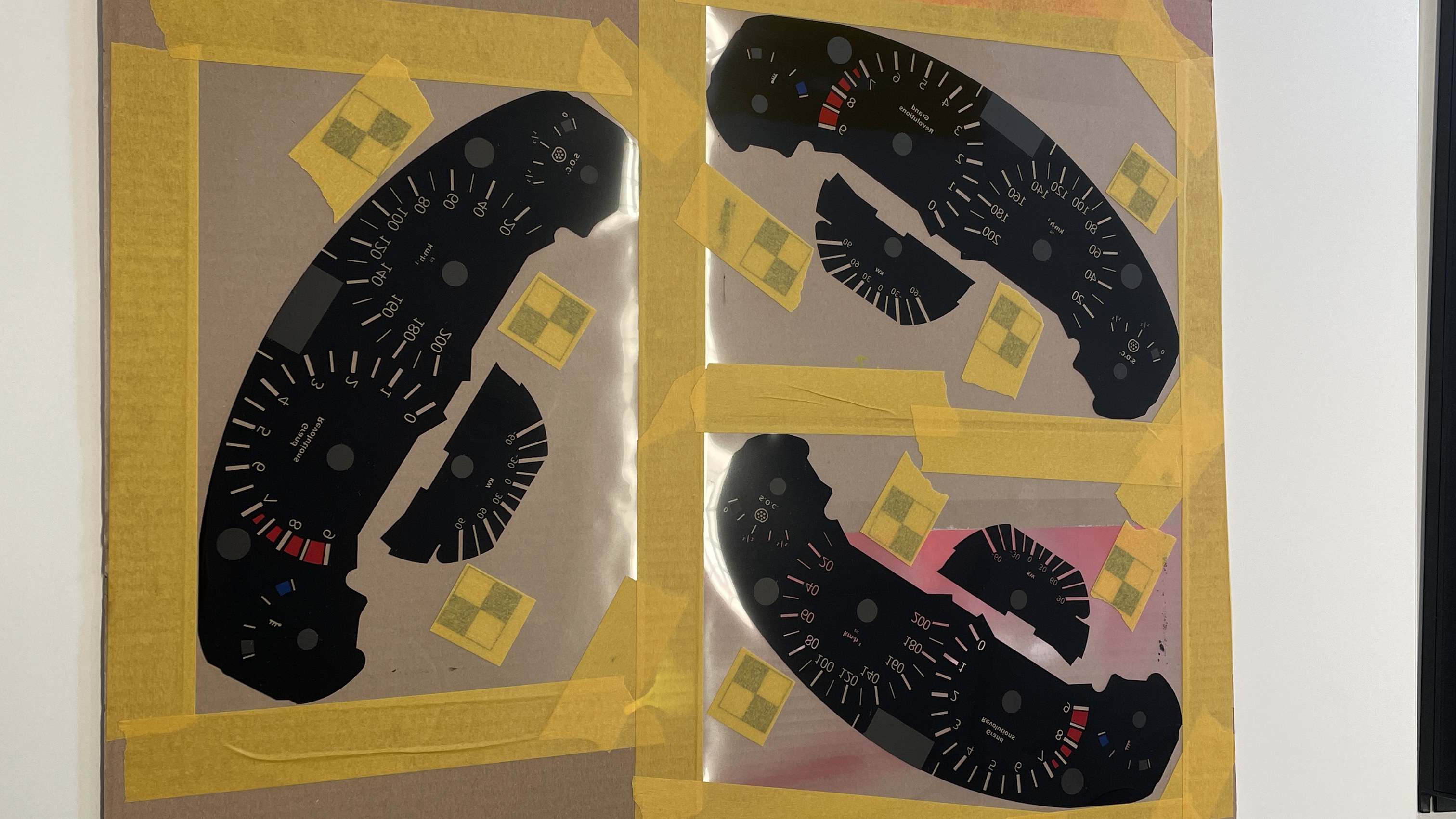
Finally, we removed the stickers from the back to reveal the areas where no spray paint was applied.
Cutting it out
After the spray paint was dry, the dial face was cut out using a laser cutter. during the design proces, a outlien cut layer was added, along with alignment marks to make sure the dial face is cut out in the right place.
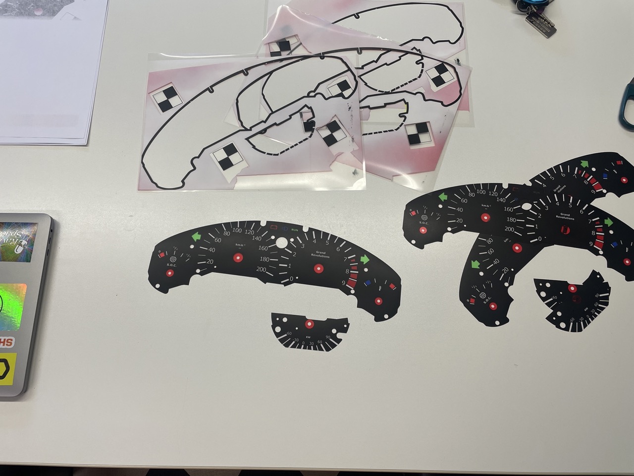
Result
The result is a dial face that is almost indistinguishable from the original dial face, aprt from the new markings. It is installed but this time, without any adhesive, so that it can be easily removed for future modifications. The dial face is held in place by the loacting fetures and the sandwich construction of the gauge cluster.
Electronics Architecture
Here we describe the electronics architecture
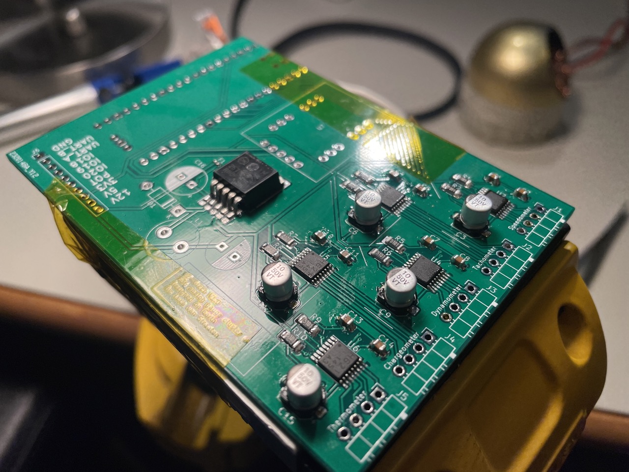
Driver PCB
A PCB was created to drive all 5 gauges. The PCB is designed to be mounted on the back of the gauge cluster, and it uses a RP2040 as the interface between the ESP32 and the gauge motors.
Software
There are two microcontrollers that need to handle spesific functions. becouse the 5 ch driver was designed before the rest of the system, its micorocntroller (the RP2040) is responsible for the gauge control. The ESP32 is responsible for the rest of the system, including the UART communication with the RP2040, the pulse counting for the speed & odometer, and the CAN communication with the BMS and motor controller.
RP2040
In synchrony with our electronics architecture, the custom firmware for the RP2040 microcontroller seamlessly integrates with the Adafruit_TLC59711 library to modulate the PWM control crucial for the gauge motors operation. The firmware delineates five unique gauges: speedometer, tachometer, dynamometer, chargeometer, and thermometer, each associated with specific pins to manage sine and cosine phase signals alongside the enable signals. The setCoilCurrent method is instrumental in orchestrating the coil currents, guided by a predefined lookup table and angle input, managing the PWM via the TLC59711 driver adeptly. The main loop is meticulously engineered to monitor serial input, facilitating real-time adjustments to either the gauge angles or the standby state, underpinning robust, interactive control over the gauge cluster operations.
Lookup Table
A Jupiter Notebook is employed to generate a Look-Up Table (LUT) to map angular positions to 16-bit duty cycle values for driving two coils in a sine and cosine fashion. Initially, the notebook processes raw data of duty cycle values and corresponding current measurements to create polynomial fits. This data is split into two segments based on a breakpoint, and a piecewise polynomial fit is constructed to better model the non-linear relationship between duty cycle and current. This piecewise polynomial is visualized alongside the raw data to verify the fit.
In subsequent cells, the notebook extends to calculate current values for sine and cosine functions based on the angular position, using the polynomials derived earlier to find the corresponding 16-bit duty cycle values for each current value. These values are then structured into a C array, forming the Look-Up Table. This LUT is used to calculate and verify the generated sine and cosine current values across the entire 360-degree range. The visualization of these results confirms the accuracy and functionality of the LUT in replicating the desired sine and cosine current profiles through the 16-bit duty cycle values.
ESP32
I ended up using an ESP32 as the main microcontroller for handling the overall system operations, including UART communication with the RP2040, pulse counting for speed and odometer functions, and CAN communication with the BMS and motor controller.
The ESP32 is very convenient for these tasks due to running FreeRTOS when used with the Arduino framework, integrated peripherals, and general availability. I did end up having the most trouble with the CAN communication, but when I got that working, the fact that you can just schedule tasks under FreeRTOS made the rest of the system integration so nice and easy to manage.
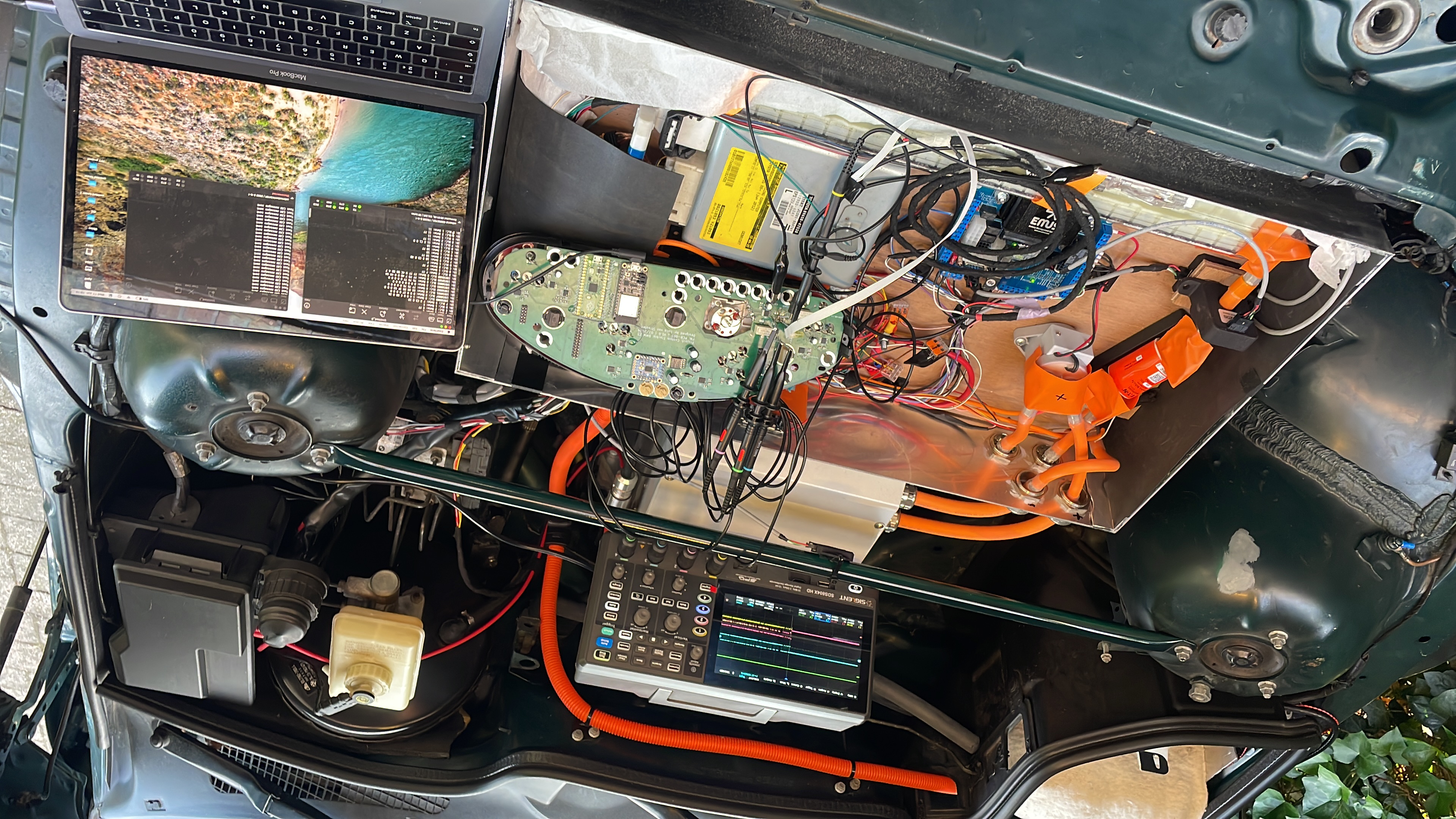
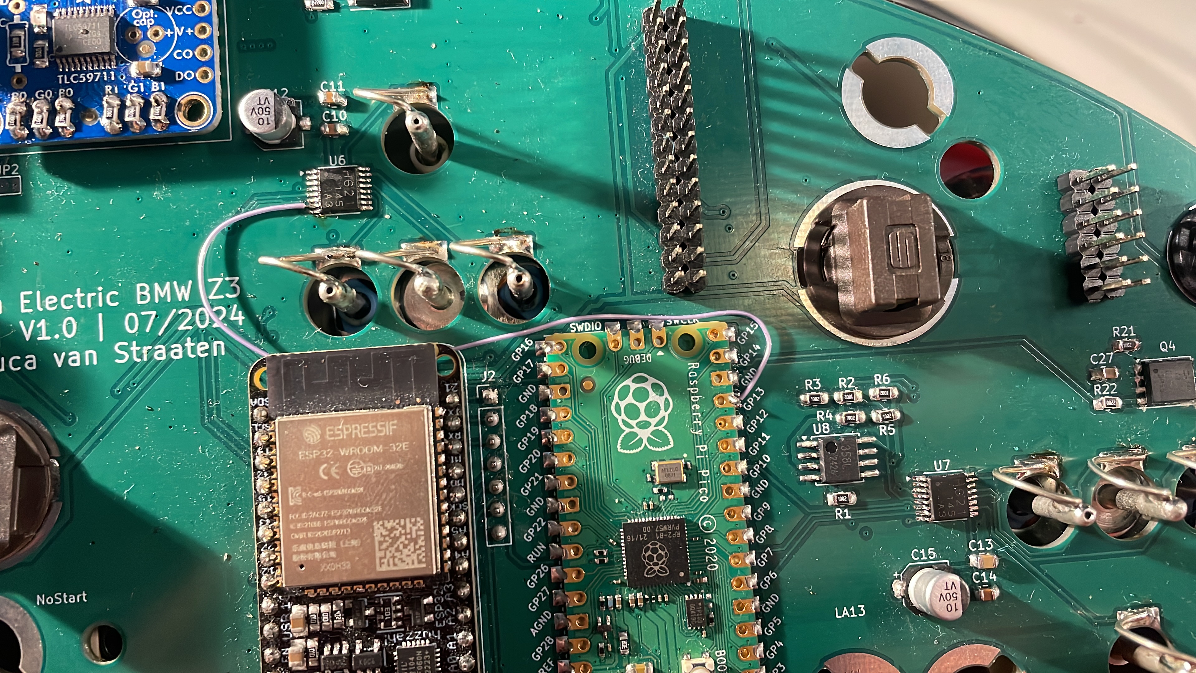
Back plane PCB
I ended up designing a new PCB which integrates the RP2040 devboard and ESP32 devboard onto a single board that fits in the cluster enclosure. I made a few mistakes, but nothing that required a respin of the PCB, just a few bodges.
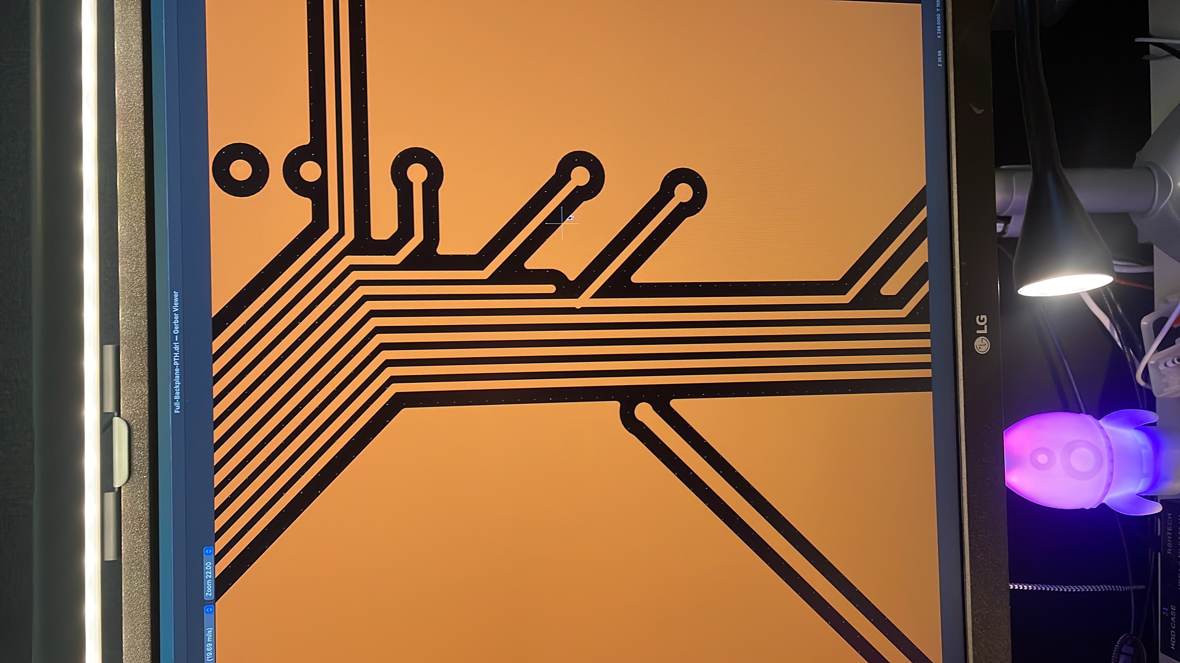
Remember to always set up automated checks, that can find these dumb mistakes automatically.